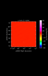
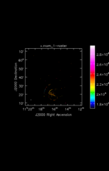
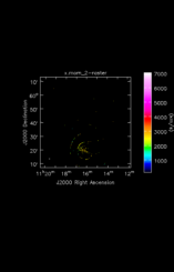
This diagram is a directed acyclic graph representing the ADMIT Task connections for the flow. Each arrow represents the connection from an ADMIT task output to the input of another ADMIT Task. The integer next to each arrow is the zero-based index of the ADMIT Task's output BDP. Note any output BDP may be used as the input for more than one ADMIT Task.
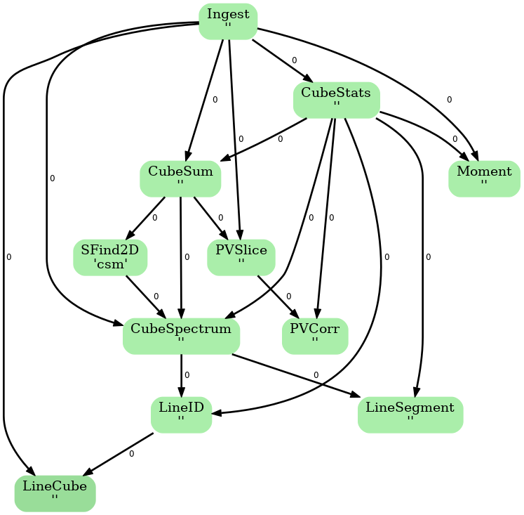

ADMIT Flow Diagram

Ingest_AT reads in a FITS image into ADMIT, creating a CASA image and extracting basic information. It is usually the first step in any ADMIT flow.


Image Information
Input image (FITS or CASA)/subaruraid/teuben/HI_image_cube0.fits
Output image (CASA) x.im
Objects1109+6041
Rest frequency1.420406 GHz
VLSR22295.2 km/s (estimated)
Beam24.00" x 24.00" PA @ 0.00 deg
Imsize661 x 661 x 1218
Intensity unitJy/beam
Data min/max-1.480E-02  /  1.757E-02
Telescopewsrt
Percentage bad pixels1.56%

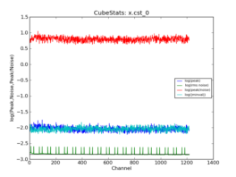
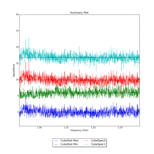
CubeStats_AT computes image-plane robust statistics on datacubes. These statistics are particularly useful for identifying spectral lines in images where the noise varies as a funnction of frequency.

CASA image x.im
RMS methodmedabsdevmed
RMS value1.456E-03
Dynamic range1.207E+01
Data mean-6.230E-09
Emission characteristics as a function of channel, as derived by CubeStats_AT (cyan: global rms, green: noise per channel, blue: peak value per channel, red: peak/noise per channel).
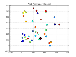
Peak point plot: Locations of per-channel peaks in the image cube x.im

CubeSum_AT sums all the emission in a cube, regardless of whether or not it comes from different spectral lines, creating a integrated map of all emission.


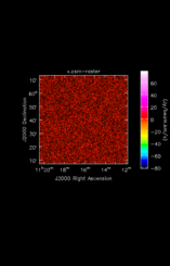
CubeSum_AT output for x.im

Integral (moment 0) of all emission in image cube

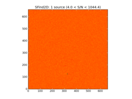
SFind2D_AT creates a list of sources found in a 2D image based on the noise statistics in the image as determined by CubeStats.

Image of input map with sources found by SFind2D overlayed in green.

Table of source locations and sizes (not deconvolved)

NameRADECFluxPeakMajorMinorPA
[][][][Jy][Jy/beam][arcsec][arcsec][deg]
1.000E+00 11:16:10.761 +59.19.44.10 1.999E+01 6.246E+01 1.350E+01 6.028E+00 1.706E+02

CubeSpectrum_AT computes spectra at one or more (x,y) positions in the datacube. Alternatively, it can produce a spectrum averaged over a box.


CubeSpectrum_AT output for image x.im

Average Spectrum at centerbox[[326pix,123pix],[1pix,1pix]]
Average Spectrum at centerbox[[11h16m10.761s,+59d19m44.10s],[1pix,1pix]]

LineSegment_AT identifies regions in one or more spectrum that have contiguous emission above a user specified noise floor. The input spectra are CubeSpectrum_AT or CubeStats_AT.


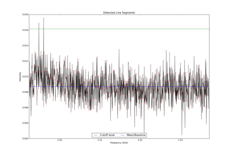
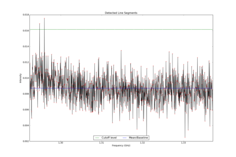
LineSegment_AT identified no spectral lines in this cube

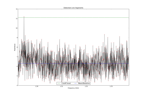
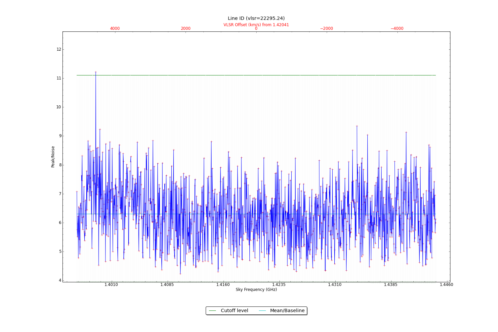
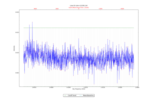
Potential lines overlaid on peak intensity plot from CubeStats_BDP.
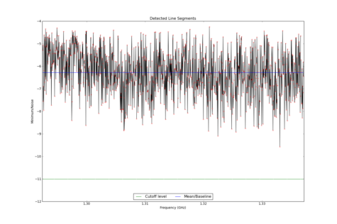
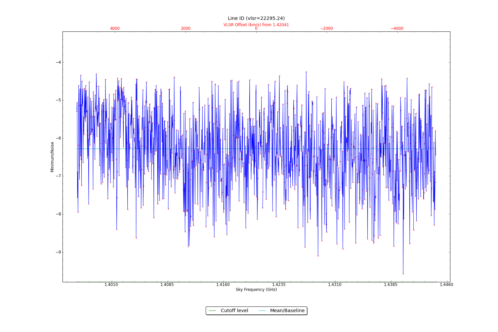
Potential lines overlaid on minimum intensity plot from CubeStats_BDP.
Detected line segments from input spectrum #0.
Detected line segments from input spectrum #1.
Identified segments overlaid on Signal/Noise plot of all spectra.

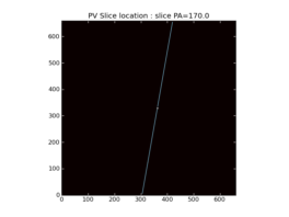
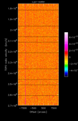
PVSlice creates position velocity diagrams through a datacube.


PVSlice_AT output for x.im

Location of position-velocity slice overlaid on a CubeSum map
Position-velocity diagram through emission centroid

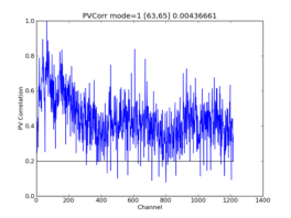
PVCorr_AT computes a cross-correlation of a PVSlice, looking for repeated patterns to detect spectral lines. For cubes with multiple spectral lines, this method can improve detection of weak ones.


PVCorr_AT output for x.pv

Position-velocity correlation plot

LineID_AT identifies spectral lines in an input datacube, using either one or more input spectra from CubeSpectrum_AT or CubeStats_AT.


Identified Spectral Lines


LineID_AT identified no spectral lines in this cube

Potential lines overlaid on peak intensity plot from CubeStats_BDP.
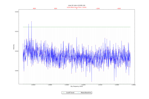
Potential lines overlaid on minimum intensity plot from CubeStats_BDP.
Identified lines overlaid on input spectrum #0.
Identified lines overlaid on input spectrum #1.

Moment_AT creates moment maps using custom clip levels.


Moment_AT output for x.im

Unidentified Moment 0 map of Source s1109+6041
Unidentified Moment 1 map of Source s1109+6041
Unidentified Moment 2 map of Source s1109+6041