Views of the insides of the WASP chassis
CSO water-cooled version
Click on most images for detailed view
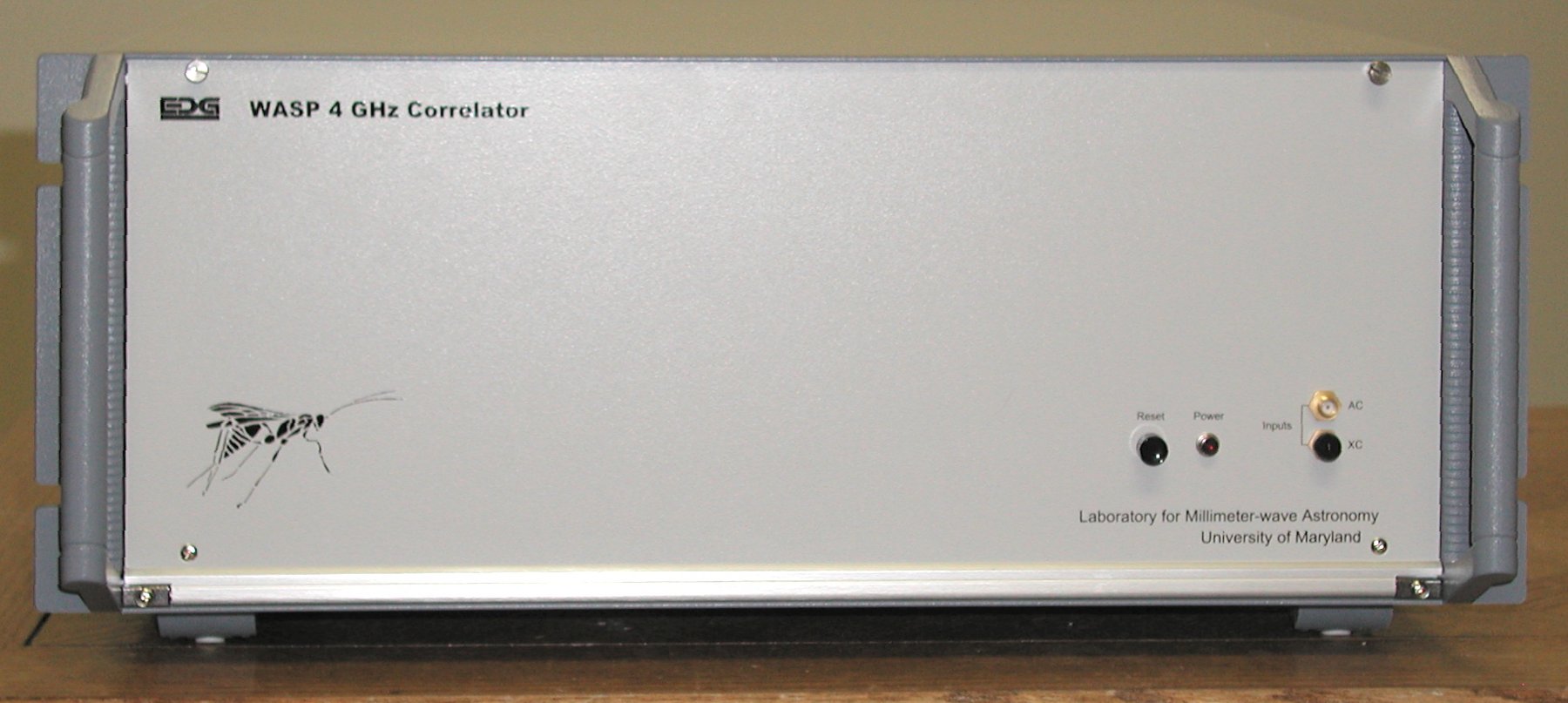
WASP2 spectrometer front panel. From left to right,
soft reset button, power lamp (+5V), and two SMA connectors for auto- or
cross-correlation signal input.

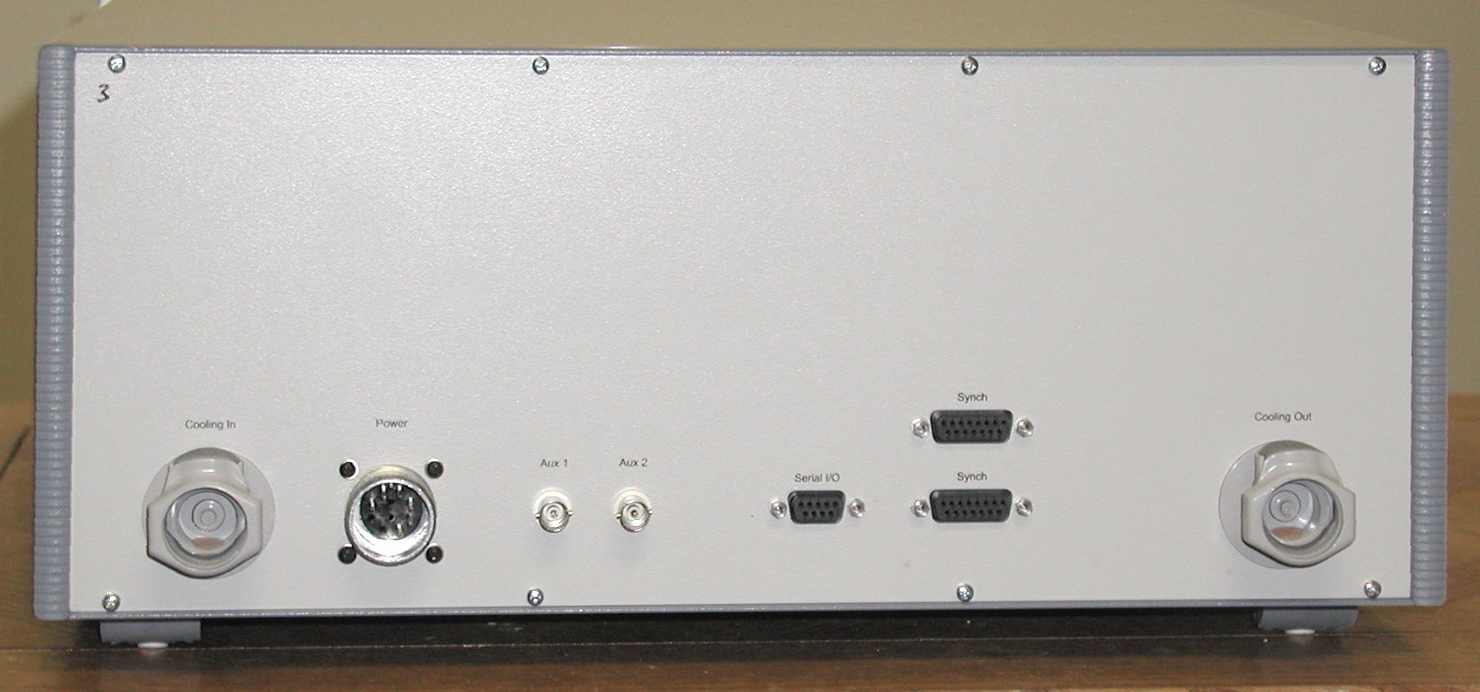
Rear view of WASP2 spectrometer. From left to right,
cooling water inlet, power supply, two BNC connectors for auxiliary I/O,
9-pin female D connector for serial I/O to the internal microcontroller,
two parallel 15-pin female D connectors for synchronization signals, and
the cooling water outlet.

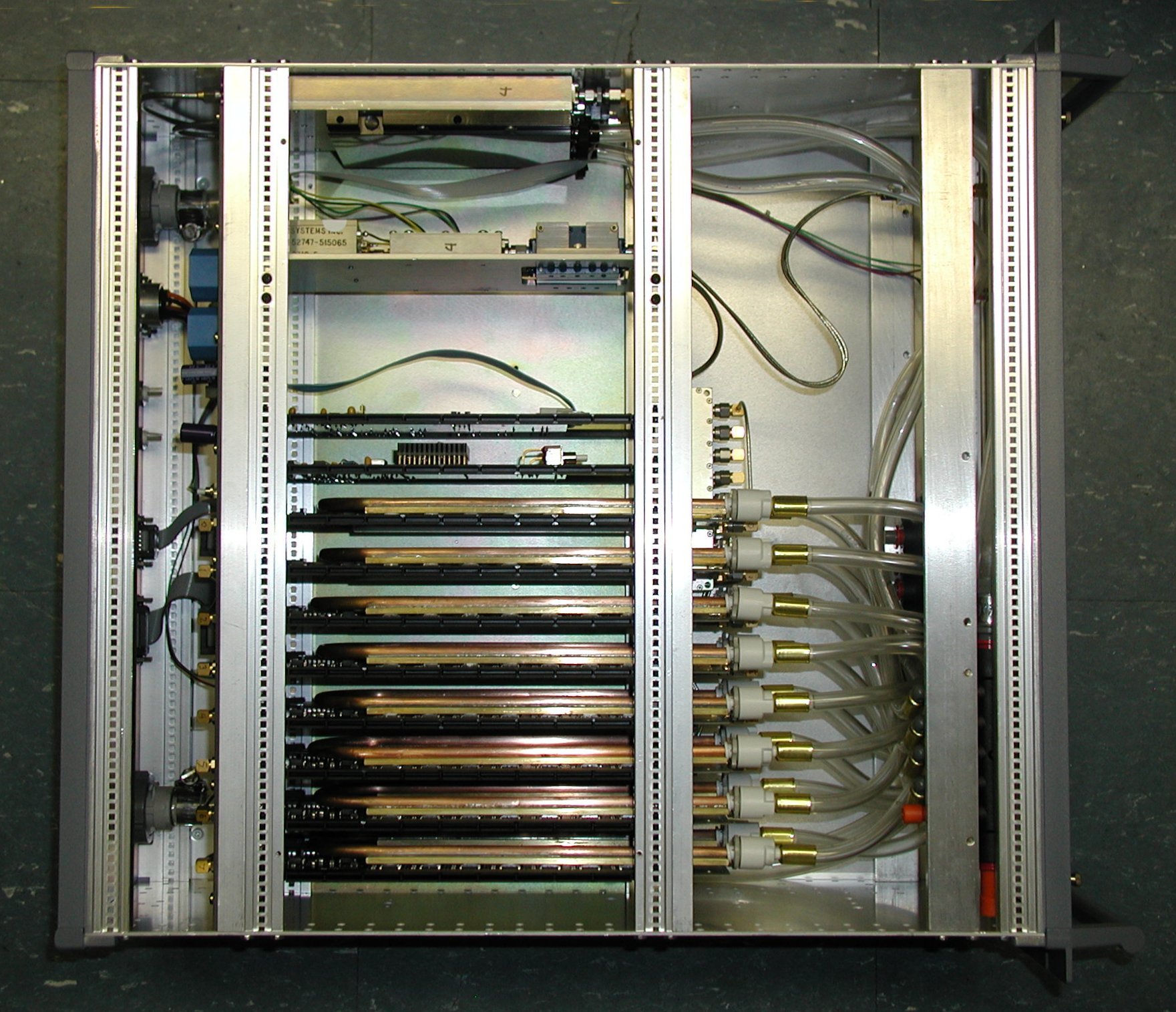
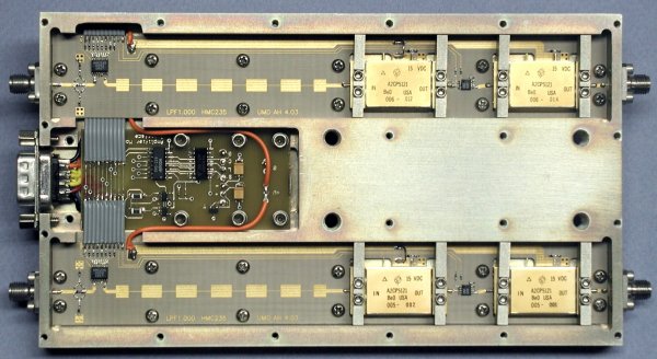
Top view of the inside of a WASP2 spectrometer chassis. From top
to bottom:
- A module containing amplifiers, attenuators, and other microwave
signal processing. The black block attached to the module is for
water cooling to stabilize the temperatures of the spectrometer
parts. Stainless steel screws and nylon washers between the module
and the chassis provide thermal isolation.
- A plate carrying parts for the dual downconverter that converts
the 4-8 GHz input band to 0-4 GHz, the spectrometer's native band.
- A circuit board with the phase switch driver, analog-to-digital
converter for temperature monitoring, and other useful stuff.
- A circuit board for the microcontroller that runs the
spectrometer and a PLD that generates clock signals for the main A/D
converters.
- Then 8 correlator cards, with 16 lags per card. The copper,
brass, and plumbing are water cooling for each card.
Bottom view of the spectrometer chassis. Two 8-way power
splitters send signals to the correlator cards with appropriate delays
provided by the coiled cables. A single long cable delay, visible
toward the bottom of the image, shifts the delay center to one end of
the spectrometer's series of lags. The clear plastic tubes at the
top and bottom carry cooling water to manifolds at the front of the
chassis (right).
Block diagram of the microwave signal processing electronics.
Images of the downconverter and amplifier modules are below.
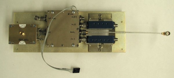
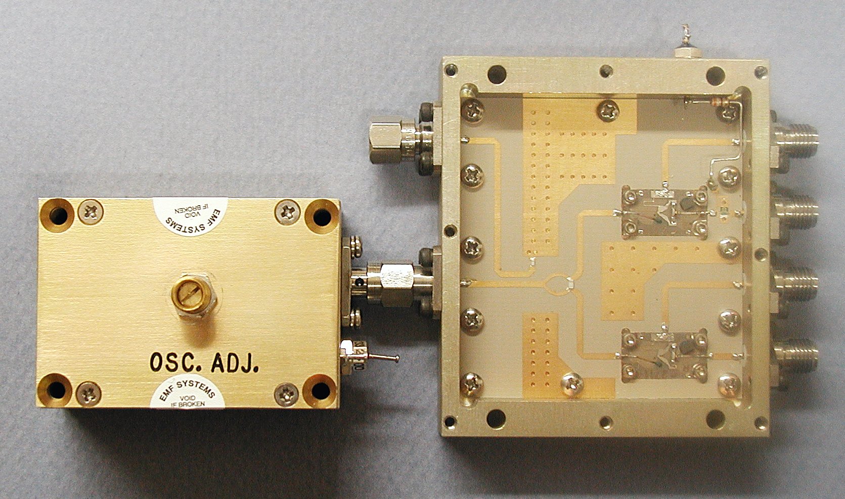
Downconverter plate with 8 GHz DRO, downconverter module, and 4-8 GHz
anti-aliasing filters.

A close-up view of DRO and downconverter module showing monitor coupler
and LO splitter feeding the two mixers. A MMIC biphase modulator
for phase switching is in the 4-8 GHz input path of the upper
channel.

A close-up image of the downconverter plate in the chassis with an
arrow showing the DRO monitor port.
The amplifier module is at the bottom of the image, with the tail of
the arrow is on the amplifier module's cooling plate.
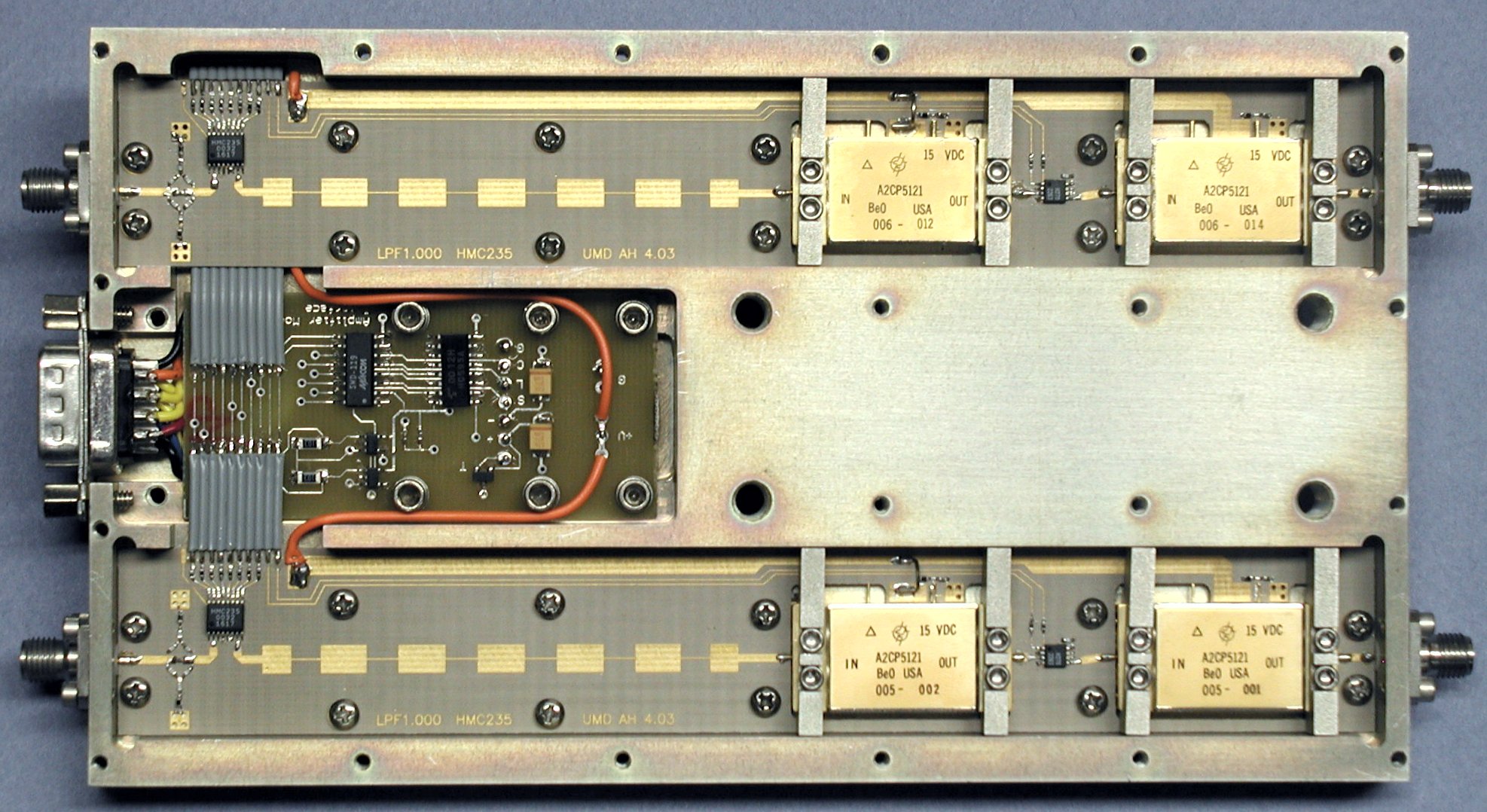
Amplifier module. From left to right, gain equalizer, step
attenuator, 4 GHz low pass filter, amplifier, switch, and
amplifier. The circuit board in the center carries the
computer interface and a temperature sensor.
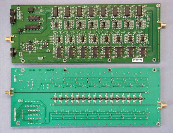
Top and bottom views of the correlator boards without cooling or
thermal covers. Each card carries 16 multipliers (bottom) and 16
corresponding preamplifiers, synchronous detector, and analog-to-digital
converters (top). More information is available on the WASP spectrometer technical page.
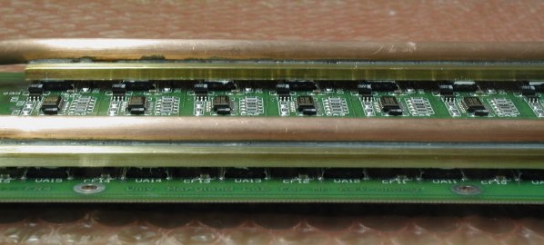
Close-up view of board water cooling. Coolant runs through the
copper tube, with the brass bars serving to collect the heat from the
ADCs. The bars are bonded to the center two ADCs on each side with
thermal epoxy; heat sink compound between the other ADCs and the bars
insures good thermal contact. We chose to cool the ADCs for two
reasons: they dissipate a moderate amount of the power, and their many
legs efficiently pull heat from the board itself.
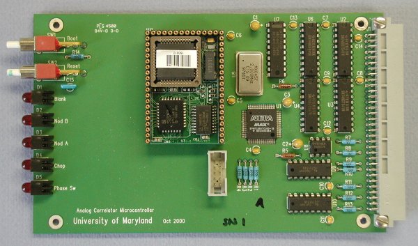
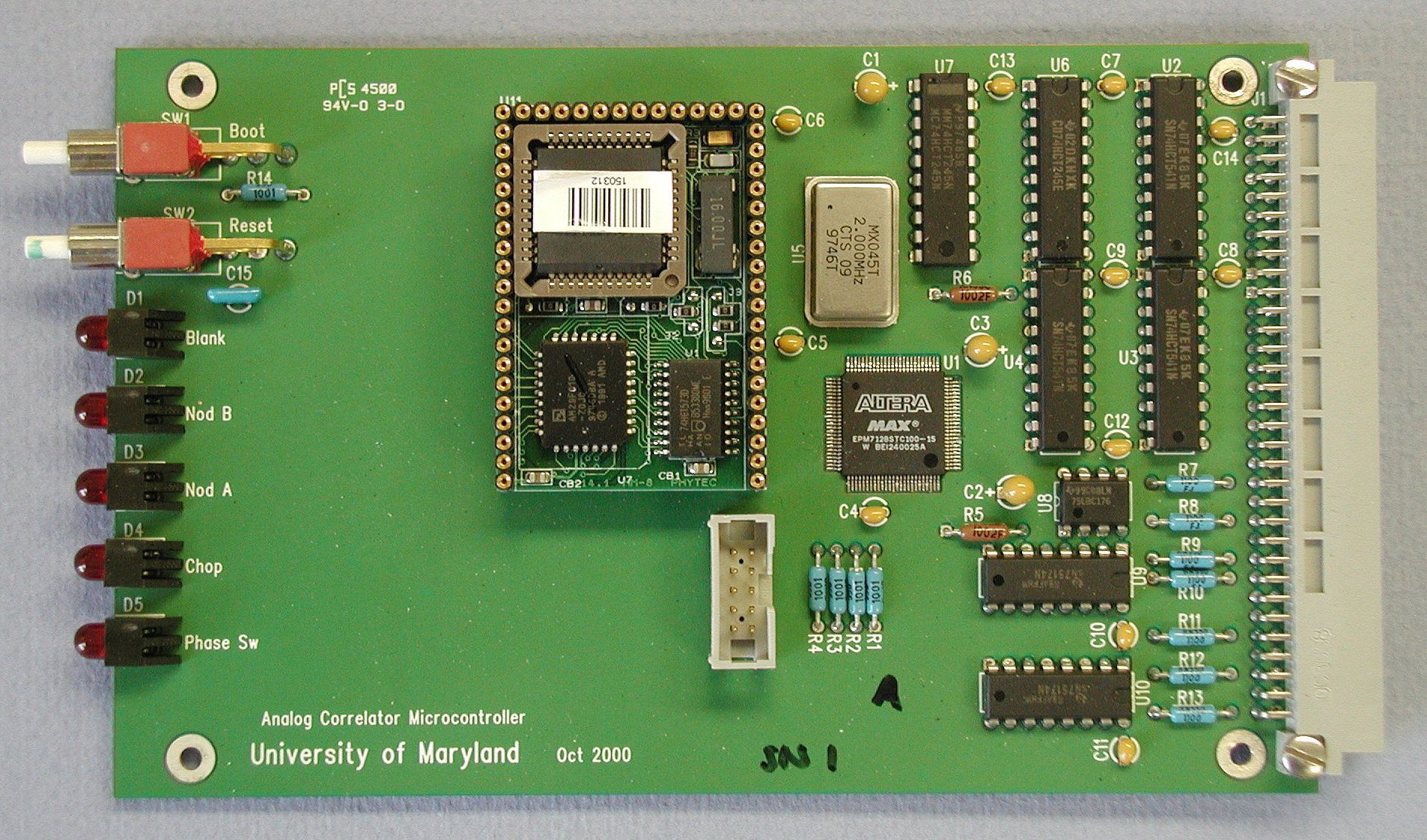
Spectrometer internal microcontroller card. The Intel 80251SB
microcontroller is a Phytec module that performs all real time
functions. An Altera PLD, programmable through the connector at
the board center, generates clock signals for the correlator ADCs.
Views of the insides of the four-WASP power supply
CSO version
Click on most images for detailed view
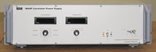
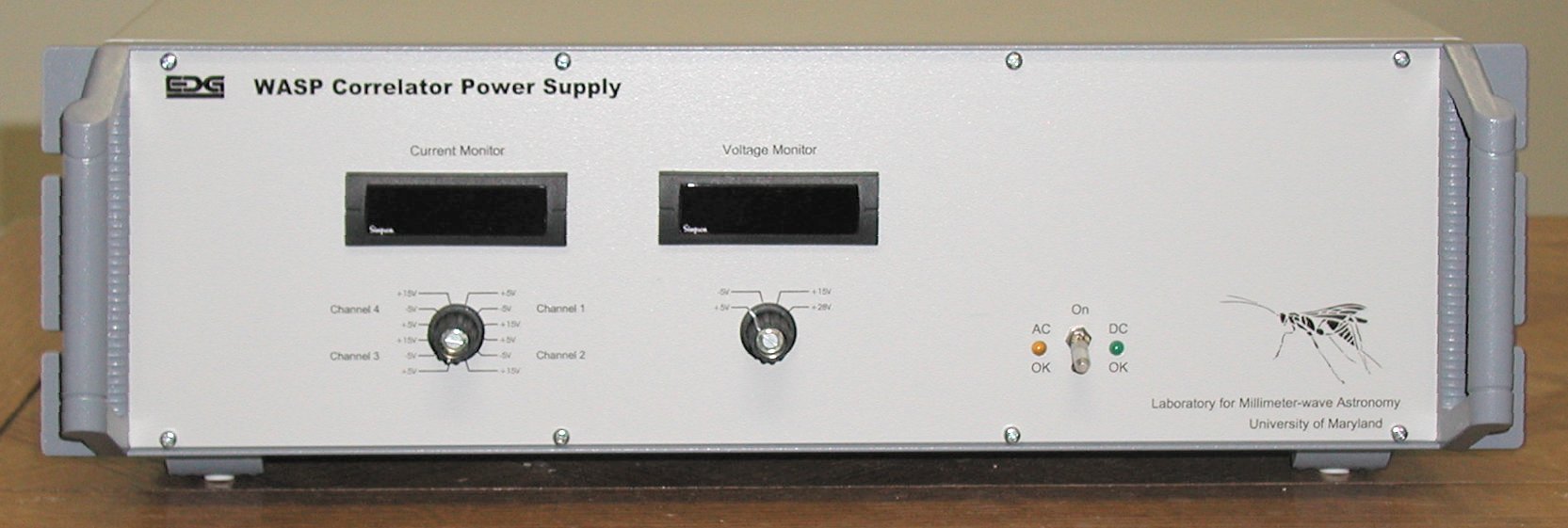
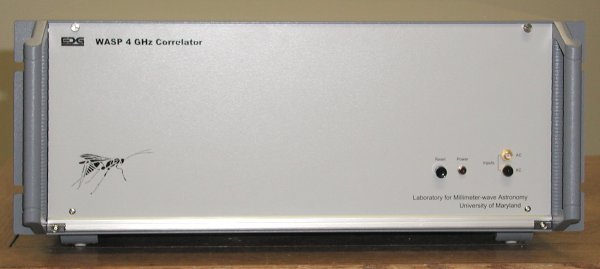
Front panel of the power supply for four WASPs. The supply
is an Astec 800 W switching supply. Meters monitor power supply
voltages and current. Lamps show AC and DC power. The
front-panel switch switches the DC power from standby to active. A
rear panel switch controls AC power.
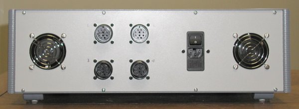
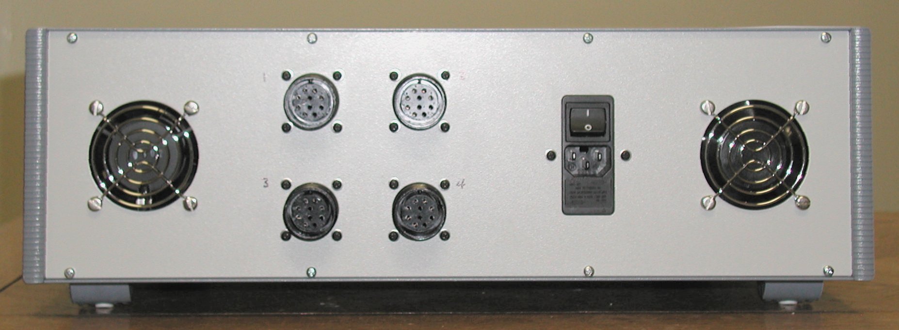
Rear panel of the power supply. In this view the fan on the left
hand side is the exhaust, and the fan on the right is the intake.
The modular line input has the line switch and line fuse.
Additional fuses are inside the box in series with each of the four
power supply connectors.
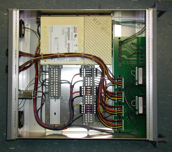
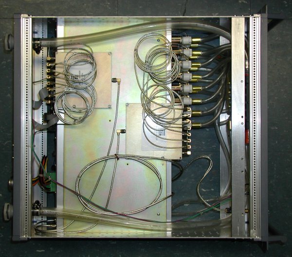
Top view of the power supply chassis. The box at the top of the
image is the power supply itself, a switching supply that supplies +5 V,
-5 V, and +15 V. Connections to the green circuit board on the
right enable monitoring of voltages and output currents. In
addition to the usual fuse on the AC power, each output line has a
separate fuse, mounted in the grey block at the chassis' center.
Unlike the spectrometers, which have water cooling, the power supply is
air-cooled. Input and exhaust fans on the chassis rear (left) help
the power supply's internal fans circulate sufficient cooling air.
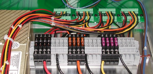
Close-up of internal fuse block. The power supply lines for each
spectrometer are individually fused.
Questions or comments? Please contact Andrew Harris.