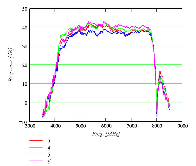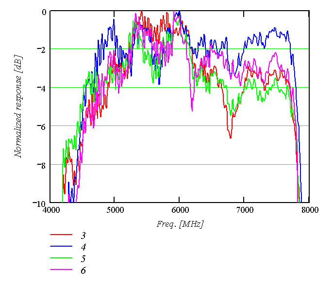

| Spectrometer number |
Board serial number |
uC code version |
Date updated |
PLD code version |
Date updated |
| First WASP2 |
none |
n/a |
n/a |
||
| 1 |
wasp223.16.11.03 |
5/28/2004 |
wasp_pld_v3 (3 kHz) |
5/28/2004 |
|
| 2 |
wasp223.16.11.03 | 5/28/2004 |
wasp_pld_v3 (3 kHz) |
5/28/2004 |
|
| 3 |
wasp223.28.8.03 | 8/28/2003 |
wasp_pld_v3 |
3/18/2003 |
|
| Spare | 1 |
wasp223.16.11.03 |
3/7/2004 | wasp_pld_v3 (3 kHz) |
3/7/2004 |
| 4 |
wasp223.20.10.03 |
1/22/2004 | wasp_pld_v3 (3 kHz) |
3/7/2004 |
|
| 5 |
wasp223.20.10.03 |
11/13/2003 | wasp_pld_v3 (3 kHz) |
3/7/2003 | |
| 6 |
wasp223.20.10.03 |
11/13/2003 | wasp_pld_v3 (3 kHz) |
3/7/2003 |
| Spectrometer number |
15 V current | Amplifier
module number |
Notes |
| 1 |
762 mA |
1 |
Amplifier wiring together in
common channel. |
| 2 |
837 mA |
2 |
Amplifiers for each branch are
wired in series; amplifier wiring from interface board is separate.
Problem with short on -5 V supply on assembly. Fixed by
loosening interface board screws, tapping, but actual cause is unknown. |
| 3 |
827 mA |
3 |
Amplifiers have separate wires
to interface board, but share common channel for each branch. Gain
shapes match well. |
| 4 |
4 |
Amplifier wiring on circuit board |
|
| 5 |
5 |
Amplifier wiring on circuit board | |
| 6 |
6 |
Amplifier wiring on circuit board |
| Item |
Mass [kg] |
| Dual downconverter |
0.570 |
| Amplifier module and input pads |
0.721 typ |
| uC and clocks board |
0.129 |
| Interface card (phsw,
thermometry, etc) |
0.083 |
| Correlator card |
0.119 |
| Correlator card with water
cooling hardware |
0.356 |
| Total correlator chassis |
9.9 |
| Total correlator chassis with
water cooling hardware and water |
14.0 |
| Power cable, 15' |
1 |
| Power supply, linear, single
correlator |
|
| Power supply, switching, four
correlator |
10.2 |
| Item |
+5 V |
-5 V |
+15 V |
Ref |
| Dual downconverter |
8 mA (phsw) |
8 mA (phsw) |
< 30 mA |
IV-116 |
| Amplifier module |
< 10 mA |
< 10 mA |
800 mA typ |
IV-116, 124 |
| uC and clocks board |
440 mA |
II-93 |
||
| Interface card |
||||
| Correlator card |
580 mA |
350 mA |
II-93, W2.4 |
| Spect |
Date |
V [V] | I [A] | V [V] | I [A] | V [V] | I [A] | P [W] |
Ref |
| 1 |
3/12/03 |
5.37 |
4.56 |
-5.17 |
2.54 |
15.16 |
0.81 |
49.9 |
IV-125 |
| 2 |
3/26/03 |
5.35 |
4.48 |
-5.19 |
2.55 |
15.06 |
0.87 |
50.3 |
IV-129 |
| Spect |
Date |
I (+5 V) [A] |
I (-5 V) [A] |
I (+15
V) [A] |
Power
[W] |
Ref |
| 3 |
3/21/04 |
4.40 |
2.52 |
0.80 |
45.9 |
V-92 |
| 4 |
3/21/04 | 4.60 | 2.59 | 0.84 | 47.9 | V-92 |
| 5 |
3/21/04 | 4.59 | 2.56 | 0.82 | 47.4 | V-92 |
| 6 |
3/21/04 | 4.54 | 2.50 | 0.84 | 47.1 | V-92 |
| Total |
18.13 |
10.17 |
3.3 |
188.3 |
| Source |
Type |
Power |
Frequency |
| Microcontroller clock |
Crystal |
CMOS |
16 MHz |
| ADC clock source |
Crystal |
CMOS/TTL |
2 MHz |
| Downconverter |
DRO |
13 dBm (20 mW) | 8.00 GHz |
| Signal |
Pin |
| Chop |
13 |
| Blank |
12 |
| NodA |
10 |
| NodB |
11 |
| Ground |
14 |
| 0-15 |
1-16 |
| 16-31 |
17-32 |
| 32-47 |
33-48 |
| 48-63 |
49-64 |
| 64-79 |
65-80 |
| 80-95 |
81-96 |
| 96-111 |
97-112 |
| 112-127 |
113-128 |