 |
Laboratory testing of WASP2 and APHID spectrometer systems. |
 |
The WASP2 circuit boards are four-layer hybrids of microwave
and normal FR-4 circuit board material. Most of the parts are
surface-mount technology, allowing the boards to be assembled by
pick-and-place robots. |
 |
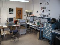
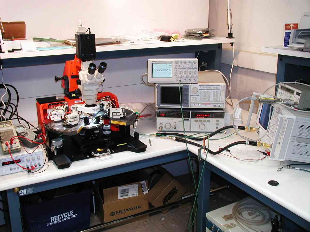
Suss PM5 probe station, oscilloscope, spectrum analyzer,
synthesizer, 40 GHz network analyzer, and other equipment set up
for testing a microwave integrated circuit |
 |
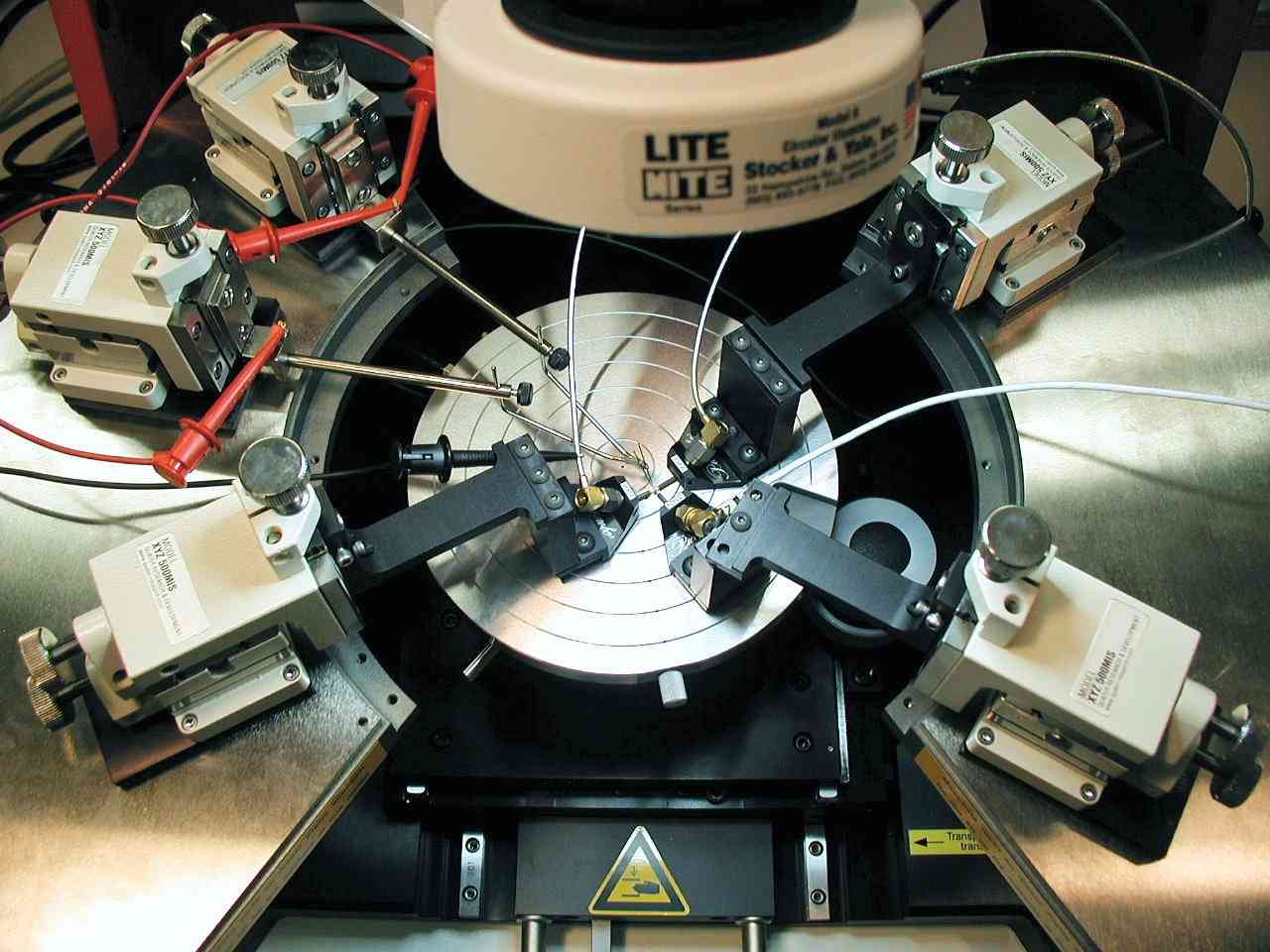
Closeup of the probe station chuck with microwave and bias
probes mounted on Quater micropositioners. |
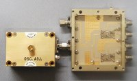 |
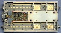
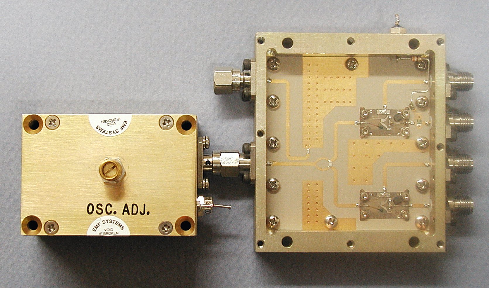
This integrated microwave module, shown with the cover open,
is a dual 4-8 GHz downconverter with a biphase modulator before the top
mixer and an LO power splitter and monitor point. The box to the
left is a commercial 8 GHz oscillator. |
 |
Our West-Bond 7400B wirebonding machine welds 0.001"
diameter aluminum and gold wires to integrated circuit chips. |
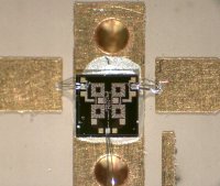 |
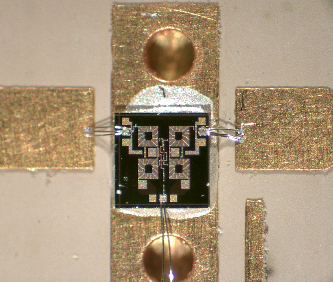
A microwave integrated circut, with size about 1 by 1 mm,
with bond wires connecting it to a circuit board. |
 |
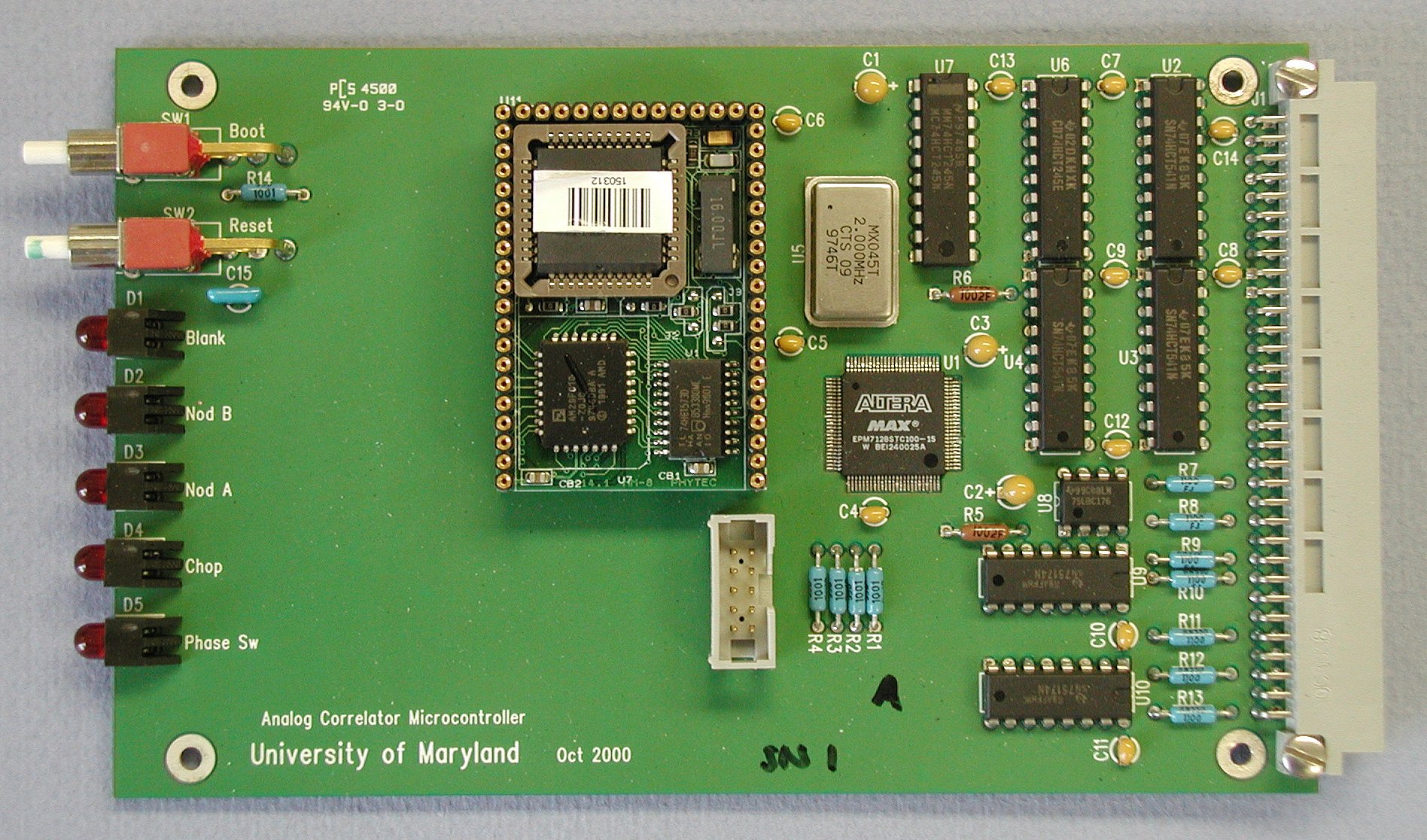
An Intel 80C251SB microcontroller handles all real-time tasks
for the WASP2 spectrometer. The ADC clock signals are also
generated on this board with a programmable logic chip. |
 |
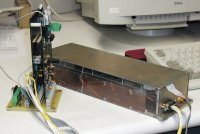
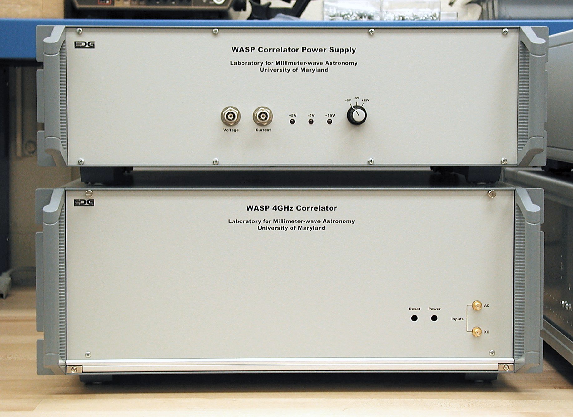
A WASP2 spectrometer (bottom, 4U chassis) and power supply
(top, 3U chassis). |
|
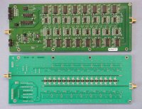
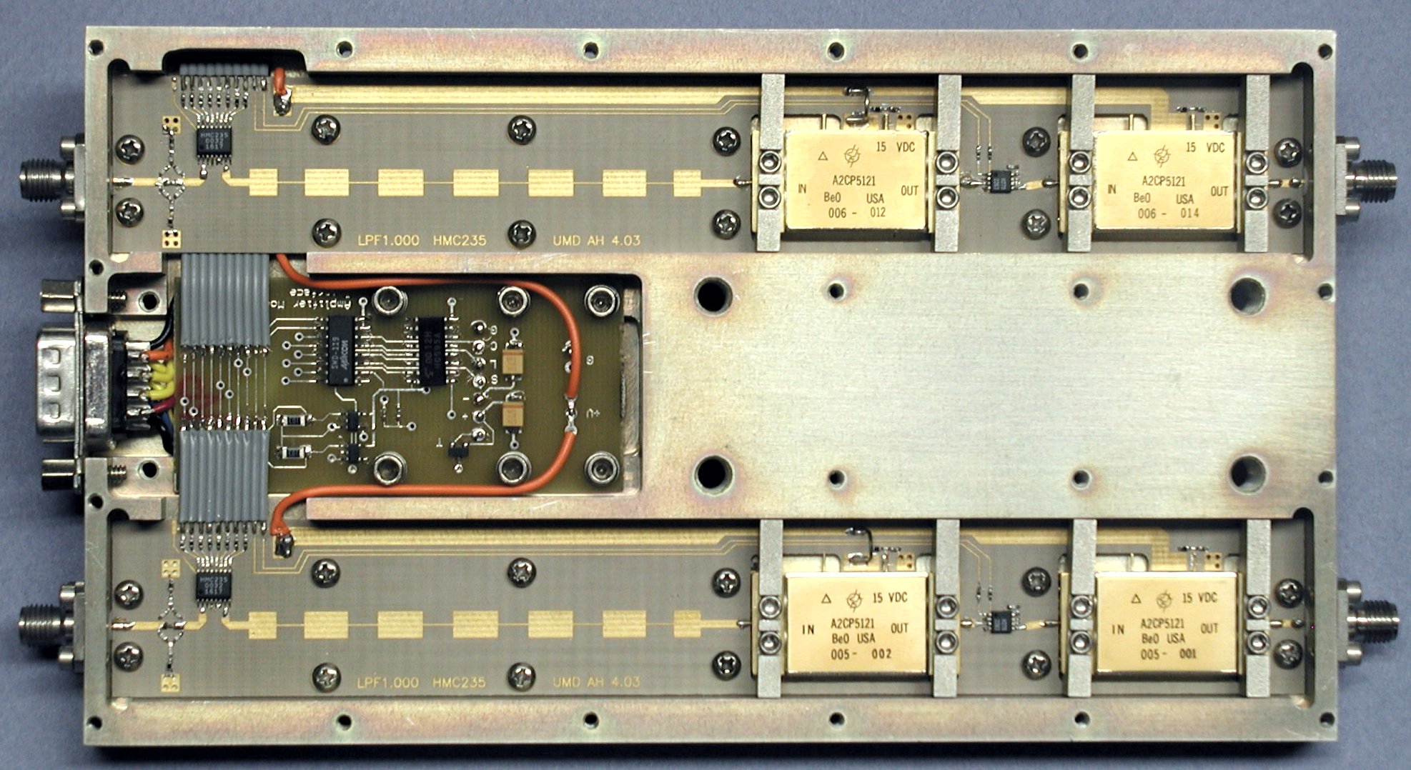
A dual-channel amplifier module for the WASP2
spectrometers. From left to right, each strip contains a gain
equalizer network, step attenuator, 4 GHz low-pass filter,
amplifier, RF switch, and amplifier. The small circuit board in
the center contains the control electronics and a serial interface to
the system computer. |
|
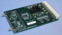
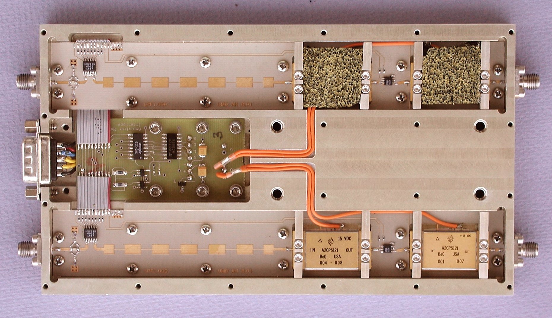
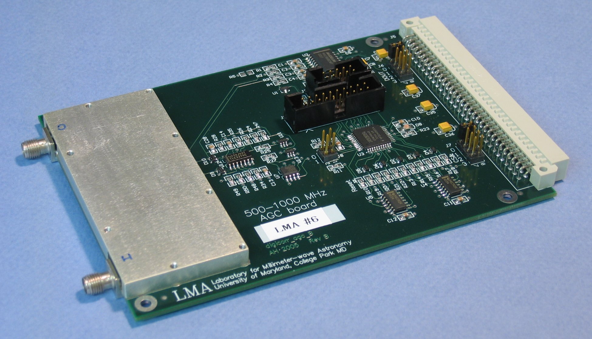
A computer-controlled
automatic gain control board for the COBRA digital correlator in the
CASIMIR instrument for SOFIA. The 500 to 1000 MHz microwave
section has two amplifier stages, step and voltage-variable
attenuators, switches for bypassing some of the attenuators, a gain
equalizer network, and power detectors at the input and output. A high-resolution image shows the board
with the shielding cover over the microwave section.
|
 |
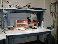
The APHID correlator module and its control computer and
electronics. This correlator uses a single WASP2 circuit board for
a 16-lag correlator with nearly 4 GHz bandwidth. When
combined with a 22 GHz receiver, the correlator measures the
emission from a water vapor spectral line to find the amount of water
over the antenna. This information can be used to "detwinkle" the
radio image measured by a millimeter wave interferometer. |


