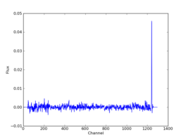
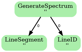
This diagram is a directed acyclic graph representing the ADMIT Task connections for the flow. Each arrow represents the connection from an ADMIT task output to the input of another ADMIT Task. The integer next to each arrow is the zero-based index of the ADMIT Task's output BDP. Note any output BDP may be used as the input for more than one ADMIT Task.
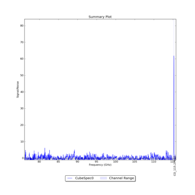
GenerateSpectrum_AT creates synthetic spectra with noise.
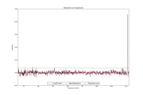
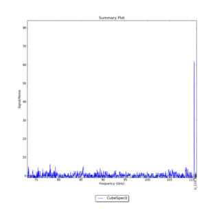
LineSegment_AT identifies regions in one or more spectrum that have contiguous emission above a user specified noise floor. The input spectra are CubeSpectrum_AT or CubeStats_AT.
Line Segments
| frequency | uid | formula | name | transition | velocity | El | Eu | linestrength | peakintensity | peakoffset | fwhm | startchan | endchan | peakrms | blend | force | [GHz] | [] | [] | [] | [] | [km/s] | [K] | [K] | [D^2] | [Jy/beam] | [km/s] | [km/s] | [] | [] | [] | [] | [] |
|---|---|---|---|---|---|---|---|---|---|---|---|---|---|---|---|---|
| 1.105E+02 | U_110.516 | NotIdentified | Not Identified | 0.000E+00 | 0.000E+00 | 0.000E+00 | 0.000E+00 | 4.592E-02 | 0.000E+00 | 2.210E+02 | 1.239E+03 | 1.244E+03 | 6.181E+01 | 0.000E+00 | False |
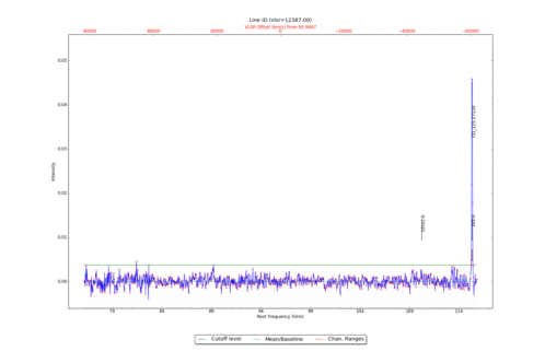
LineID_AT identifies spectral lines in an input datacube, using either one or more input spectra from CubeSpectrum_AT or CubeStats_AT.
Identified Spectral Lines
Identified Spectral Lines
| frequency | uid | formula | name | transition | velocity | El | Eu | linestrength | peakintensity | peakoffset | fwhm | startchan | endchan | peakrms | blend | force | [GHz] | [] | [] | [] | [] | [km/s] | [K] | [K] | [D^2] | [Jy/beam] | [km/s] | [km/s] | [] | [] | [] | [] | [] |
|---|---|---|---|---|---|---|---|---|---|---|---|---|---|---|---|---|
| 1.153E+02 | CO_115.27120 | CO | Carbon Monoxide | 1-0 | 1.237E+04 | 0.000E+00 | 5.532E+00 | 1.212E-02 | 4.592E-02 | -2.055E+01 | 1.177E+01 | 1.239E+03 | 1.243E+03 | 6.181E+01 | 0.000E+00 | False |
