
- Note: The etalon weight is 19.5 kg, not including the mounting plate.
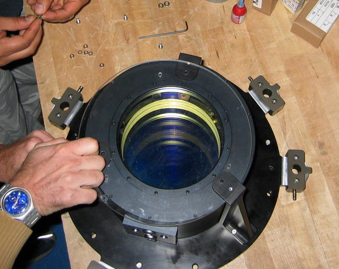
- If the MMTF etalon is not attached to its mounting plate, attach
it. The orientation of the etalon is important. In the left
figure below, the CS-100 cable ports are in the correct rotational
orientation (at the bottom of the picture) with respect to the
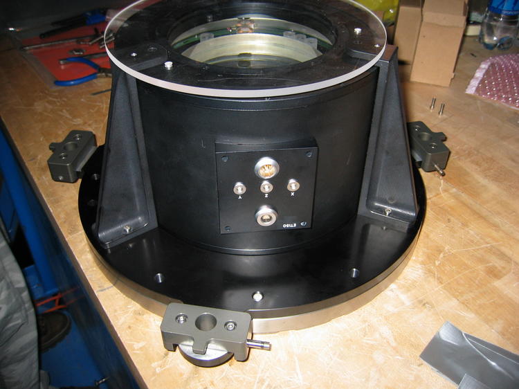
mounting plate flanges. In the right figure below, the ports are such
that the etalon is right-side up.
A top view of the MMTF, attached to its mounting plate. Note the correct orientation of the CS-100 cable ports (at bottom) with respect to the mounting flanges. (Click for a larger image.)
A side view of the MMTF, attached to its mounting plate. Note the correct orientation of the CS-100 cable ports, ensuring that the etalon is right-side up. (Click for a larger image.)
- Ensure that the two clear, protective covers covering the etalon aperture are in place.
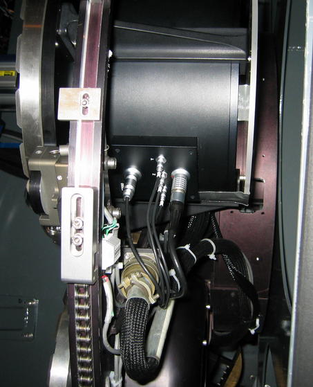
- Secure the etalon in the disperser wheel using the same procedure
as for other IMACS gratings. In the disperser wheel service position,
the MMTF cable sockets will be pointing out and down, as shown in the
image below (in the "5 o'clock" position as viewed from the rear of
the instrument, looking toward the telescope).
A view of the MMTF when mounted in the disperser wheel, with CS-100 cables connected. (Click for a larger image.)
- Plug into the MMTF the 5 cables connecting the etalon to the CS-100 controller. Be sure that the X, Y, and Z cables are matched properly with their respective sockets.
- Remove the two covers protecting either side of the etalon aperture.
1. Install the intermediate-band blocking filters specified by the observer.
2. Install MMTF slit mask ID #2049. This mask will be used for checking the position of the optical axis.
3. If charge-shuffling has been specified by the observer, insert MMTF slit mask "A".
WARNING: Never set the Zcoarse dial on the CS-100 below -2! Doing so may damage the etalon coating.
CAUTION: The cables between the CS-100 controller and etalon should never be attached or removed while the CS-100 power is on.
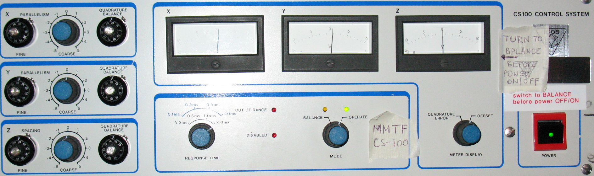
Front panel of the CS-100. (Click for a larger, more readable image.)
The CS-100 is the electronic brain of MMTF. It is located in the IMACS electronics rack. For a more detailed description than that provided here, read the CS-100 manual.
Features
- Mode Knob. In Balance mode, changes to the etalon controls balance out the capacitance bridges in the feedback loop, but do not move the etalon plates. In Operate mode, changes to the controls affect the position of the etalon plates.
- Xcoarse, Xfine, Xquad, Ycoarse, Yfine, Yquad (X and Y coarse, fine, and "quadrature balance" knobs). The X and Y settings control the degree to which the etalon plates are parallel by tilting one of the plates around two axes parallel to the plate surface. The coarse and fine knobs control the actual tilts, while the quad knobs fine-tune the electronic balances.
- Zcoarse, Zfine, Zquad (Z coarse, fine, and "quadrature balance" knobs). The Z settings control the spacing between the plates ("piston" motion).
- LED indicators. There are 4 indicators in the center of the panel. (1) The green Operate light indicates that the etalon feedback loop is on and working properly. (2) The orange Balance light indicates that Balance mode is enabled. (3) A red Out of Range light when the etalon is in Operate mode signifies that the etalon is not properly balanced. (4) The red Disabled light illuminates when control of the CSS-100 is taken over by the IMACS computer. (The CS-100 front panel controls do not work when the computer has control.)
- Meters. The three meters show how far away the X, Y, and Z feedback loops are from being balanced. The center position ("0") indicates balance.
- Meter Display Knob. In the Offset position, the meters respond to changes in Xfine, Yfine, and Zfine. In the Quadrature Error position, the meters respond to changes in Xquad, Yquad, and Zquad.
- Response Time Knob. This knob controls how quickly the etalon responds to requested changes in X, Y, and Z. It should be set to 2.0 ms.
Initial Configuration
- Ensure that the Mode knob is in the Balance setting. Power on the CS-100.
- Ensure that the CS-100 Meter Display knob is set to
Offset. Using the knobs on the left side of the CS-100, dial
in the following numbers to balance the capacitance feedback loop and
parallelize the etalon. Replace ? with the
Zcoarse specified by the observer.
coarse fine quad X -1 7.11 4.20 Y 0 6.80 3.78 Z ? 4.10 4.34 - Turn the Mode knob to Operate. After a few seconds, the Operate light should illuminate, indicating the feedback loop is now in active operation and functioning properly. If instead the Out of Range light illuminates, the etalon must be re-balanced; follow the balancing instructions.
Changing Zcoarse
Follow this procedure.