
The MMTF sits in the disperser wheel of the IMACS camera:
|
The optical path through IMACS and the MMTF. |
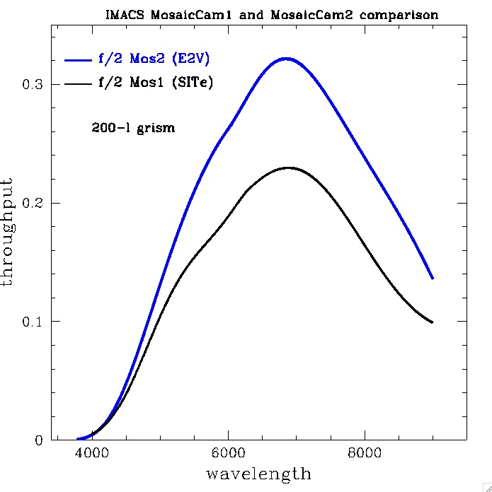
Throughput curves for the old (black curve) and new, red-sensitive (blue curve) IMACS cameras. The new camera is more sensitive at all wavelengths, and 50% more sensitive at 7000Å. |
The MMTF consists of 3 major components: the etalon and its support assembly, the CS-100 controller, and the cables connecting them.
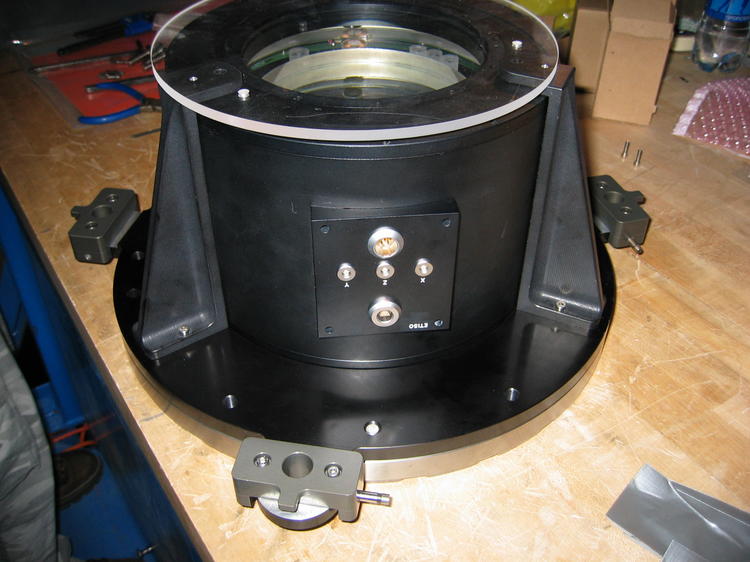
A side view of the etalon, ensconced in its mechanical mount.
The etalon consists of two parallel plates composed of fused silica, each with a 150 mm clear aperture. The etalons are separated by a tunable air gap, with minimum and maximum separations of 1.3 microns and 10.7 microns. The plates are coated on the interior side (the side facing the other plate) with a reflective coating consisting of a multi-layer dielectric. (The finesse of the etalon is a function of the interior reflective coatings.) The exterior surfaces are anti-reflection coated. The plates are smooth at the λ level.
Capacitors and piezoelectric stacks lie near the plate edges. The voltages across the capacitors are used to measure the tilt and spacing of the plates. The stacks move the plates in three dimensions: a tilt around two axes (X and Y) and spacing along the Z axis. The tilt of the plates governs their parallelism; the best (most symmetric, and most flux in the peak) instrumental profile is achieved when the plates are most parallel. The spacing controls both the wavelengths transmitted and the width of the instrumental profile.
The CS-100 controller sends and receives electronic signals from the etalon to control the tilt and spacing of the plates. Once they are made parallel, the controller operates an electronic feedback loop to keep the etalon plates in position. The coarse values for tilt and spacing (Xcoarse, Ycoarse, and Zcoarse) are set using the dials on the CS-100 controller. The tilt and spacing can be changed in smaller increments using Xfine, Yfine, and Zfine values. The fine values can be changed using either the CS-100 dials or the IMACS control software. The observer should not change the etalon settings with the CS-100 controller dials.
Note: (X, Y)coarse and (X, Y)fine control the etalon parallelism. However, the coarse spacing Zcoarse controls the etalon bandpass, while the fine spacing Zfine governs the transmitted wavelength. The fine spacing can affect the bandpass, but only when changed by a large amount.
For more details on the CS-100, read the CS-100 documentation or a summary on the TTF website.
The etalon connects to the CS-100 through shielded cabling that runs from IMACS to the electronic cooling rack on one side of the Nasmyth platform.
The entire system was manufactured by IC Optical Systems Ltd.
Observers have full freedom to tune the central wavelength of the MMTF bandpass within the range allowed by a particular blocking filter. The wavelength can be tuned from one exposure to the next, or within a given exposure (see the charge shuffling / frequency switching observing mode). A blocking filter is required to select only one transmission order (a given plate spacing transmits multiple wavelengths at a single location, each corresponding to a different order).
The currently available order blocking filters are listed below.
Each has a bandpass intermediate between that of broad-band filters
and that of the etalon. For each filter, we list the central
wavelength and full-width at half-maximum in the IMACS beam, and
provide a transmission curve. (The transmission curves were measured
in a collimated beam, and are corrected to the IMACS f/2 beam; the
correction is not exact.) We also provide a link to a table of etalon
parameters at the relevant wavelengths, including FWHM values.
| λ (Å) | FWHM (Å) | Transmission | Etalon Parameters | |
|---|---|---|---|---|
| 5102 | 150 | plot | data | table |
| 5290 | 156 | plot | data | table |
| 6399 | 206 | plot | data | table |
| ~6600 | ~260† | plot | data | table |
| 6815 | 216 | plot | data | table |
| 7045 | 228 | plot | data | table |
| 8149 | 133 | plot | data | table |
| 9163 | 318 | plot | data | table |
†FWHM > free spectral range.
If you are considering the purchase of a narrow-band filter not listed here and are interested in making it available for use with MMTF, or have other questions about filters, please contact Sylvain Veilleux. Filter bandpasses must fall in the high-reflectivity part of the interior plate coating transmission curve; this range is roughly 5000-9500 Å (see Figure).
![]()
Transmission curve of the reflective etalon coating.
Changing filters between exposures is straightforward. However, each filter requires its own set of calibrations to determine the wavelength solution and etalon parallelism. It is thus important to plan ahead and find wavelength solutions for each filter during the day before a run. The observer is limited to the use of at most 2 filters in a single night because of calibration overheads.
For a given order, the area of approximately constant wavelength at
image center, or monochromatic spot, depends on wavelength only
through the finesse. For MMTF, the coating transmission is fairly
constant above 5500 Å. However, the diameter of the spot does
depend on plate spacing. We list here representative values for
several different wavelengths and spacings:
| Wavelength (Å) | DJ (Zcoarse=-2) (arcmin) | DJ (Zcoarse=3) (arcmin) |
|---|---|---|
| 5100 | 13.81 | 10.71 |
| 6600 | 11.6 | 8.5 |
| 9150 | 11.5 | 9.5 |
1At 5100 Å the numbers are ~1'-2' higher due to a drop in finesse.
The available instrumental full-widths at half maximum are linked in the table above. For 6600 Å, the range is 6 - 13 Å. (The "effective bandpass", or the integral of the profile divided by its peak, is ~60% larger than the FWHM for a Lorentz distribution; the MMTF instrumental profile is approximately Lorentzian.) The FWHM values at other wavelengths, for a fixed plate spacing, scale with λ2. For a fixed wavelength, the FWHM is adjusted by making large changes in the plate spacing (d in the physical domain, Zcoarse in the electronic domain). In summary,
FWHM(λ) ≅ λ2 / [2 d Finesse]
where the Finesse is mostly constant, except at the edges of the etalon's coating response. At the edges of the coating transmission curve (see Figure above), the reflectivity (and hence the etalon finesse) drops, broadening the profile and increasing its FWHM. Thus, at 5100 Å, the FWHM range is 8 - 14 Å. These values are slightly higher than at 6600 Å, while one would expect lower values for a constant finesse.
The bandpass can be changed during an observer's run only under exceptional circumstances.