Parallelism is the process by which the two etalon plates are made parallel to one another. If the plates are not optimally aligned, the transmission profile will be broad and/or asymmetric. This diminishes the light transmitted in the core of the profile, and thus the system throughput (for an emission-line source) and the instrumental resolution. It is thus crucial that proper parallelism is achieved and maintained throughout the run.
Parallelism is achieved and maintained through a capacitor and piezo-electric feedback system. See this page for a brief description.
The parallelism is optimized by the instrument scientist prior to the run. However, the parallelism depends on two variables: (1) wavelength, due to changes in the behavior of the multi-layer reflection coating with wavelength; and (2) the rotation angle of the etalon, probably due to gravity-induced sag of the plates that remains uncorrected by the system feedback mechanism. Rotation is inevitable during the course of a run, as the IMACS camera rotates to maintain a constant orientation of the CCD mosaic with respect to the sky. Fortunately, the rotation effect is reproducible as is outlined below. The observer should check the parallelism roughly every half hour, after every large telescope movement, and when the filter is changed.
There are several methods for achieving parallel plates. We have developed a simple procedure that relys on scanning the transmitted image in the radial coordinate to prodcue a spectrum. The plate alignment is scanned along both axes of movement using a (M x N) grid of [Xfine, Yfine]. At each value of [Xfine, Yfine], an image is taken of an emission line. Each image is then azimuthally averaged to create an emission-line spectrum. The profiles of emission features are compared by eye (and, where possible, with line fits) to find the narrowest and most symmetric profile. This procedure is discussed below, followed by a separate procedure for quickly determining the drift in X and Y with gravity angle.
The table below has parallelism values that have worked in the past for various filter and Zc arrangements. Use of these values will bring the etalon close to parallel but will still require a careful parallelization using the procedure below.
| Filter | Zc=-2 | Zc=+1 | Zc=+3 | |||
|---|---|---|---|---|---|---|
| X | Y | X | Y | X | Y | |
| 5100 Å | 1990 | 2090 | 2025 | 2125 | 2025 | 2100 |
| 5300 Å | 1995 | 2075 | 2000 | 2075 | 2015 | 2075 |
| 6400 Å | 2010 | 2115 | 2025 | 2100 | 2035 | 2035 |
| 6600 Å | 2020 | 2125 | 2025 | 2100 | 2050 | 2100 |
| 6815 Å | 2050 | 2170 | 2100 | 2175 | 2100 | 2160 |
| 7050 Å | 2105 | 2225 | 2150 | 2225 | 2120 | 2175 |
| 8200 Å | 2240 | 2305 | 2275 | 2250 | 2275 | 2250 |
| 8650 Å | 2265 | 2375 | 2280 | 2300 | 2300 | 2275 |
| 9150 Å | 2300 | 2375 | 2300 | 2335 | 2315 | 2300 |
Here is a detailed procedure:
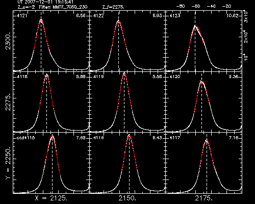
The output of ringplot. The optimal parallelism values are [Xfine, Yfine] ~ [2150, 2275], as evidenced by the symmetric peak at these values and small width (re: the rough sigma values in the upper right-hand corners).
- Choose a lamp appropriate for the filter being used. (See this table for options.)
- If this is the first time during the run: With the lamp on,
adjust the fine etalon spacing Zfine and take snapshot
images until you observe a bright emission line well separated from
other lines in the field of view. The ring should be isolated from
other lines, and its radius should be approximately halfway between
the center and edge of the aperture. If a single, well-separated
emission line is not present, a doublet will serve.
Warning: Using a double or blended line can make it VERY difficult to parallelize. Always use a single line if possible (you may have to try other lamps).
- If this is not the first time: Select the same Zfine value used for previous parallelism tests in this filter.
- In the Script menu, click Create to bring up the script creation window. Choose Parallelize and enter the starting [Xfine, Yfine] (x, y), step size in X and Yfine (dx, dy), and number of steps in X and Yfine (nx, ny). Assuming the image does not saturate, use 8x8 on-chip binning to minimize the readout time. Click Exec to bring up the script execution window, and run the loop.
- When the script has finished, create the spectra by typing the
following in a terminal:
% ringbatch 1 9 6600 --fast [--ms 1]
where 1 and 9 are the starting and ending frame numbers (leading zeros ignored) and 6600 is the central wavelength of the filter. The '--fast' option is good for parallelism tests, as it decreases the pixel sampling rate and thus increases the processing speed. For noisy data (faint lines), the '--ms 1' option smooths the spectrum using a median filter of width 1 Å. - Plot the spectra in a grid of [Xfine, Yfine]
values by running the following:
% ringplot 1 9
To do a Voigt fit of the profile peak, add --fit to the end of the command. - Search for the [Xfine, Yfine] that optimizes the etalon transmission profile. The optimal profile will be peaky (at or near the peak flux), narrow, and symmetric.
- If necessary, take another grid of spectra with different starting and ending values of [Xfine, Yfine] until the optimal parallelism settings are found.
- Enter the chosen [Xfine, Yfine] pair into the IMACS software.
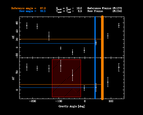
The output of xydrift. The gravity angle of the reference and new frames are shown in orange and blue, respectively. The change in X and Y are calculated to be -10.5 and -8.3. The "Danger Zone", marked in red, is avoided in this instance.
Once properly parallelized, the etalon plates should remain parallel for all time. However, there is a fairly strong correlation between the gravity angle and the plate spacing, suggesting that the glass is sagging under gravity. We advise observers to operate at a constant gravity angle, nudging IMACS back to Θgrav ~ 0° before each exposure, as outlined in the following procedure . However, if you do not wish to use this method of observing, the following will be necessary.
Any time the telescope moves, whether a large motion across the sky or small motions due to tracking, the parallelism should be checked. Luckily, the changes in X and Y as a function of gravity angle are largely reproducable and thus a lookup table can be used to predict how X and Y will change.
Using xydrift, the change in gravity angle between two exposures can be converted to a change in X and Y. The proper syntax to run xydrift is:
% xydrift 13 25
This will calculate the change in X and Y, assuming that the etalon was parallel for exposure 13. Once the proper offsets to X and Y have been applied, the observer must also check the wavelength calibration using ringdrift, since a change in X and Y always corresponds to a change in Z.
Warning: For reasons which remain unclear, the parallelism values become extremely difficult to predict for gravity angles between -120 and -20, a region dubbed the danger zone. If you are currently working in the danger zone, you should parallelize carefully using the full-blown procedure outlined above.


